Arduino Radar Project – Ultrasonic Based Radar – Connection and Code
Creating an ultrasonic-based radar project with Arduino involves using an ultrasonic sensor (like the HC-SR04) to detect objects and display their distance. Here’s a simple guide on how to set it up, including wiring and code.
Components Needed
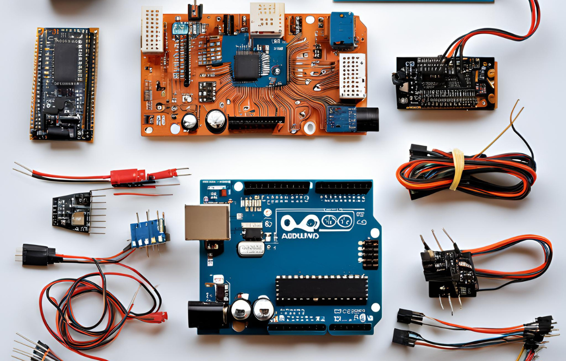
1. *Arduino Board* (e.g., Arduino Uno)
2. *HC-SR04 Ultrasonic Sensor*
3. *Breadboard and Jumper Wires*
4. *LED (optional, for indication)*
5. *Resistor (for LED, typically 220Ω)*
6. *Power Source (USB or battery)*
Wiring Connections
1. *HC-SR04 Connections:*
– VCC → 5V on Arduino
– GND → GND on Arduino
– TRIG → Digital Pin 9 on Arduino
– ECHO → Digital Pin 10 on Arduino
2. *Optional LED:*
– Connect the anode (long leg) to a digital pin (e.g., Pin 13) through a 220Ω resistor.
– Connect the cathode (short leg) to GND.
Arduino Code
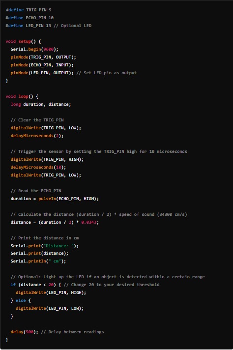
Here’s a simple example code to get you started:
Explanation of the Code
1. *Pin Definitions:* The code starts by defining which pins the TRIG and ECHO of the ultrasonic sensor are connected to.
2. *Setup Function:* Initializes serial communication and sets the pin modes.
3. *Loop Function:*
– It triggers the ultrasonic sensor by sending a high signal on the TRIG_PIN.
– Measures the duration it takes for the echo to return.
– Calculates the distance based on the speed of sound.
– Prints the distance to the Serial Monitor.
– If the detected distance is less than a certain threshold, it lights up the LED.
Testing
1. Upload the code to your Arduino.
2. Open the Serial Monitor (set to 9600 baud).
3. Observe the distance readings. Move an object in front of the sensor to test detection.
Notes
– Ensure proper power supply to avoid unexpected behavior.
– You can adjust the threshold for the LED as per your requirement.
– For radar-like visualization, consider using a display or a graphical representation, which will require additional components and coding.
Feel free to modify the code and connections based on your project requirements!

